Since the algorithm operation of STPMS is quite complicated and implemented by pure software, in order to maintain STPMS in the best state or solve problems and perform software FW updates remotely in the most effective way, and use STPMS in an environment where the car has wireless networking, Therefore, OTA is used to achieve this purpose, as follows:
Use OTA to automatically update software that has solved problems through remote updates to avoid losses.
Use OTA new features.
Use OTA updates to troubleshoot and solve problems.
This article explains the STPMS OTA operation technology for the situation where STPMS is placed in a TBox. The same principle can be applied to the situation where STPMS is placed in an IVI or driving recorder.
OTA overall architecture
STPMS OTA encrypts the software Bin file to be updated into the FW file to be updated, and places it in the cloud for TBox to download via wireless network (such as 4G) and store it in the TBox inside the car as a Flash file. Then the FW file is written into the Bin file Flash of STPMS according to the defined protocol according to the schedule. After the update is completed, it is restarted to take effect and the new software is running. Details are as follows
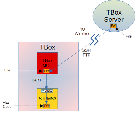
As shown in the figure above, the main units involved in STPMS FW update include TBox Server, TBox MCU, and STPMS module.
TBox MCU and TBox Server are connected through 4G wireless network, while TBox MCU and STPMS are connected through NMEA UART.
Submit the updated version of STPMS FW and place it on TBox Server first, ready to be downloaded to TBox Flash.
According to the plan to update STPMS FW, TBox Server selects the TBox/STPMS to be updated and cooperates with TBox MCU through 4G wireless transmission. OTA to TBox Flash is stored in flash memory space. This program can use SFTP (SSH FTP) The agreement will be carried out or executed in accordance with the existing TBox agreement.
When TBox MCU completes storing STPMS FW to TBox Flash and checks that the content passes, it notifies STPMS via NMEA UART to perform STPMS FW update.
After receiving the notification, STPMS is set to the STPMS FW update mode, then reboots into the STPMS FW update operation mode, and performs the FW update according to the established operating protocol.
The STPMS program writes the new version of STPMS FW into Code Flash and immediately performs a self-reset/reboot restart after completing the FW update. If the restart is successful, the normal functions of the new version of STPMS will be restored, and the new version of FW will be restarted. If it is unsuccessful, STPMS will notify TBox MCU of this situation, and TBox MCU will re-execute the STPMS FW update program.
Detailed program operation is specified in the Operation Agreement section.
OTA packet format
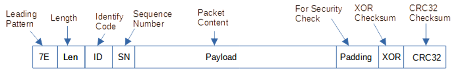
OTA consists of fixed data packet content, and the entire software Bin file unit is packaged according to this data packet format. The detailed description is as follows:
The updated version of STPMS FW is submitted in the form of a Binary File, but the file content is stacked in packages of a specific format.
The packet format definition of this specific format is shown in Figure 2 (before 7E Exception is made), and the respective descriptions are as follows:
7E (Byte 1): This is the Leading Pattern of this packet, used for header identification.
Len (Byte 2~3): The length of the packet. The packet length is specified in Bytes according to ICD (excluding header 7E and Len).
ID (Byte 4): The specific ID of this package, determined according to different package characteristics.
SQ (Byte 5~6): The sequence number of this packet, starting from 1 and increasing by 1 in sequence.
Payload (Byte 7~Byte M): The data content of this package. The first package defines the Information of this Image File as the basis for the update operation, and subsequent packages contain FW data.
Padding (Byte M ~ Byte 1040): used as Security Check to prevent theft and tampering. The size of the M value is randomly adjusted according to the encryption method.
XOR (Byte 1041): This package contains the XOR check code in Byte, excluding 7E.
CRC32 (Byte 1042~ Byte 1045): This package contains CRC32 check code in 32Bits, excluding 7E, but including XOR.
The above are all data values without 7E, 7D Exception, and then do 7E, 7D Exception plus Baotou 7E.
This Binary File can be sent to TBox MCU by TBox Server in the form of a file or a specific protocol and stored in TBox Flash. Then it is sent to STPMS in packet units through UART through the operation protocol with STPMS. Finally, it is converted into an Image Code by the STPMS program. Into STPMS Flash, it is a mapping file executable in STPMS.
The first packet is an information packet (SN=0), with a length of about 215 Bytes (according to ICD). The content is to update the FW firmware information. After the second packet, it is firmware data, with a length of about 1045 Bytes (according to ICD). specified), the last packet is marked with a specific ID, specified in the ICD.
TBox and STPMS are based on 7E when defining the start and end of a packet. The header byte of each packet is 7E, and the byte before the next 7E is the tail byte of the packet. When the package content is formed, the value of the data 7E will be converted to 7D 02, and then the value of 7D will be converted to 7D 01. Therefore, 7E will not appear in the package content after 7E until the end of the package.
OTA header package
It should be noted that the first package of each packaged FW download file is a specific package (Header Packet), which is used as the content information to update the FW file, so that the update can be completed safely and without errors, as detailed in the figure below.
OTA operation protocol
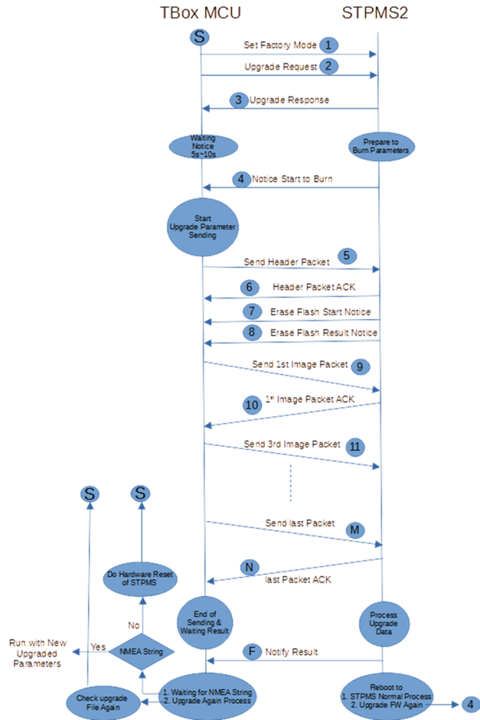
The OTA update protocol and process are shown in the figure below. After TBox downloads the FW update file, it can start the update according to the schedule. The startup method is to first send Set Factory Mode to STPMS to enter the update mode, and then send the Upgrade Request to officially update. The details are as follows.
The protocol is divided into two parts: 1. The TBox Server downloads the STPMS FW file or data format to the TBox Flash operation. 2. The TBox MCU transmits the STPMS FW file or data content to STPMS for FW refresh.
The first part of the operation method: TBox Server and TBox MCU first create the Socket required for file transfer (such as SSH) through the 4G wireless network, and then download the STPMS FW file data completely to TBox Flash flash memory space. As for which Socket and protocol to use, you can make your own decision. As long as you can ensure that the STPMS FW file can be downloaded to TBox Flash completely and without error, there is no guarantee that the file content will be hijacked or tampered with (this security issue will be verified and protected by BGI itself. crime prevention). After the download is completed, check the XOR and CRC32 checksum of each package to see if the download is complete and correct.
The second part of the operation method and agreement are as follows:
TBox MCU reads the downloaded STPMS FW file data content. The reading method is in packet units, that is, the previous Byte data content from the beginning of 7E to the next 7E header.
First read the first package: it contains version information, update information and security usage (Security Usage), as shown in Figure 4. You can use this information to check whether the downloaded file content is correct and determine whether to perform this update. Details Set in ICD.
After confirming that the update is to be carried out, send the entire first package to STPMS via NMEA UART to confirm the update content when starting the firmware update process. After entering FW Upgrade Mode, execute the update program. The method and protocol are as follows.
TBox MCU first sends the request to enter FW Upgrade Mode to STPMS.
After STPMS confirms this request, it replies that TBox MCU can enter FW Upgrade Mode. Otherwise, TBox MCU can do Retry if it cannot enter FW Upgrade Mode.
After entering the FW Upgrade Mode and confirming the execution, STPMS will first reply to do STPMS auto-restart. The TBox MCU will wait for about 5 seconds for STPMS to complete the restart and execute the FW Upgrade program.
After restarting, TBox MCU will be replied and STPMS has officially entered FW Upgrade Mode.
TBox can send the first Header Packet information package to STPMS for confirmation.
After STPMS confirms the information package, it must first erase the Flash firmware update space, and will notify TBox to start erasing and the required erasing time (about 10 seconds).
After TBox waits for this erasure time, STPMS completes the erasure and then notifies TBox that the erasure has been completed.
After confirmation, TBox can start sending the STPMS FW package to be updated.
TBox MCU sequentially reads the specific firmware packages starting with 7E one by one starting from the first package, and sends each package to STPMS through NMEA UART.
After receiving it, STPMS will reply (ACK) to TBox MCU: whether STPMS successfully received this packet (checked by the check code and related information), including the SQ value of the packet.
STPMS will also perform a Security Check after receiving this specific packet to confirm whether the content has been tampered with or has errors. If there is an error, a failure code will be returned to the TBox MCU to take corresponding actions. The details are specified in the ICD.
If the STPMS ACK is successful, the TBox MCU will continue to send the next packet. If the ACK fails, the TBox MCU will resend successfully (at least Retry three times).
In this way, each package is sent in sequence until the last package is sent. STPMS will first reply that it has been completely received, including whether the reception was successful. If the reception fails, a failure code will be returned.
After the reception is completed and successful, STPMS will perform a complete update of FW. After the update is completed, it will notify TBox MCU that the update has been completed, and then restart STPMS by itself. After about five seconds, TBox MCU will start to receive normal NMEA packets sent by STPMS, indicating that the updated FW is operating normally.
If STPMS returns an update failure message, corresponding follow-up actions will be taken based on the invalidation code returned, as detailed in the ICD.
If the TBox MCU receives abnormally sent NMEA information after the STPMS FW update is completed and restarts successfully, the TBox MCU will notify STPMS of the abnormal situation and take corresponding follow-up actions based on the code returned by STPMS, or decide on its own to reset the TBox Server downloads the FW File and then performs the above FW update procedure again, as detailed in the ICD.
If the above update failure occurs, TBox MCU must restart the MCU in hardware and then try to update again. The update may be repeated three times at most.
OTA update operation
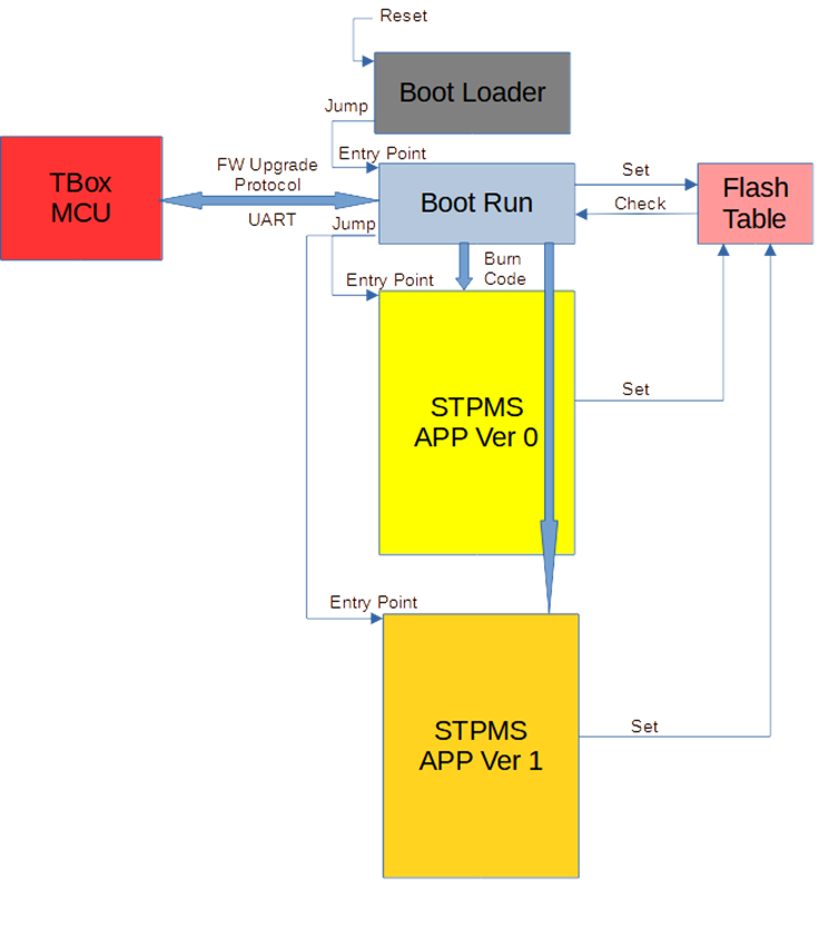
The internal update diagram of STPMS is as shown in the figure above. After STPMS Reset, it first enters the Boot Loader (ROM) program, and then the Boot Loader starts the Boot Run (Flash) program. The Boot Run determines which version to jump to (Jump) based on the Flash Table. FW Image executable program. In the HD8089 chip module, you can only jump to one FW Image execution program. If the Image cannot be executed normally, you can only ask the TBox MCU to update the FW program to return to normal. In the OTA approach of next-generation chip modules, if the Image cannot be executed normally, it can jump back to the FW Image that can be executed originally. This is the role of backup (Redundancy) to update the FW Image.
Before Boot Run jumps, it must write a specific value in the Flash Table to indicate that it will jump to the desired FW Image execution program and start the Watchdog Timer operation. After the jump to the FW program is successfully executed, it must be written back to the Flash Table for execution. Successfully confirms the value and updates the Watchdog Timer normally so no reboot occurs. If the jumped FW program fails to execute successfully, the Watchdog Timer cannot be updated. After Time Out, it will restart to the Boot Run program for execution. In this way, Boot Run will know that the jumped FW Image just failed to execute and communicate with TBox. Follow-up processing.
The above protocol operation considers the worst-case scenario: TBox MCU must re-request the TBox Server to download the available FW File and then perform FW updates according to the protocol program to restore the normal operation of STPMS. TBox must consider how to implement the overall operation process of this worst-case scenario.
OTA features
The OTA update mechanism of STPMS has high reliability characteristics and can ensure that STPMS will not be unusable due to OTA update failure.
The OTA FW download file of STPMS has the functions of error content detection and content tampering prevention.
The operation protocol between STPMS's OTA and TBox is simple and reliable, and has a re-update function, which greatly reduces TBox's resource investment when implementing this OTA.
Honghe Technology also provides the source code of the program code that runs on TBox. TBox can be integrated with slight modifications and can quickly complete the STPMS OTA integration function.
STPMS also has three built-in checksum codes, including CRC32, XOR32 and ADD32. The chance of updating data errors is less than one billionth.